
 10 hours Ago By Al Williams
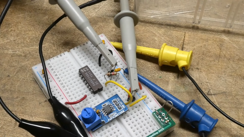
[IMSAI Guy] grabbed an obsolete XOR gate and tried a classic circuit to turn it into a frequency doubler. Of course, being an old part, it won’t work at very high frequencies, but the circuit is super simple, just using the gate and an RC network. You can see a video of his exploration below.
The simple circuit seems like it should work, but in practice, it needed an extra component. In theory, the RC circuit acts as an edge detector. So, each edge of the input signal causes a pulse on the output as the second input lags the first.

That sounds good, but it looked terrible on the scope until a 1K resistor tied to the capacitor shifted the bias point of the gate. In all fairness, the original schematic used a Schmitt trigger gate, which may have made a difference had one been available. There were slight differences, though, depending on the type of device.
An LS part, for example, didn’t need the extra resistor.Of course, an RC network is just one way to delay the input, and the delay determines the width of the output pulse and constrains the input frequency and duty cycle. However, you could use other gates, including the other XOR gates in the package to realize a fast delay.
Frequency doublers are very common at microwave frequencies, but they don’t work in the same way. There are several ways to do it, but a common method is to use a nonlinear element to generate plenty of harmonics and then filter off everything but the second one. Or the third one, if you wanted a tripler instead.
.